open_loop_uplink_power_control#
- sionna.sys.open_loop_uplink_power_control(pathloss: torch.Tensor, num_allocated_subcarriers: torch.Tensor, alpha: float | torch.Tensor = 1.0, p0_dbm: float | torch.Tensor = -90.0, ut_max_power_dbm: float | torch.Tensor = 26.0, precision: Literal['single', 'double'] | None = None) torch.Tensor[source]#
Implements an open-loop uplink power control procedure inspired by 3GPP TS 38.213, Section 7.1.1 [3GPP38213].
For each user, the uplink transmission power \(P^{\mathrm{UL}}\) is computed as:
\[P^{\mathrm{UL}} = \min \{ P_0 + \alpha PL + 10 \log_{10}(\mathrm{\#PRB}), \ P^{\mathrm{max}}\} \quad [\mathrm{dBm}]\]where \(P^{\mathrm{max}}\) is the maximum power, \(P_0\) [dBm] is the target received power per Physical Resource Block (PRB), \(PL\) is the pathloss and \(\alpha\in [0,1]\) is the pathloss compensation factor.
Note that if \(\alpha=1\), the pathloss is fully compensated and the power per PRB received by the base station equals \(P_0\) [dBm], assuming \(P^{\mathrm{max}}\) is not reached. Lower values of \(\alpha\) can help reducing interference caused to neighboring cells.
With respect to 3GPP TS 38.213, additional factors such as closed-loop control and transport format adjustments are here ignored.
- Parameters:
pathloss (torch.Tensor) – Pathloss for each user relative to the serving base station, in linear scale. Shape: […, num_ut].
num_allocated_subcarriers (torch.Tensor) – Number of allocated subcarriers for each user. Shape: […, num_ut].
alpha (float | torch.Tensor) – Pathloss compensation factor. If a float, the same value is applied to all users. Shape: […, num_ut] or scalar. Defaults to 1.0.
p0_dbm (float | torch.Tensor) – Target received power per PRB [dBm]. If a float, the same value is applied to all users. Shape: […, num_ut] or scalar. Defaults to -90.0.
ut_max_power_dbm (float | torch.Tensor) – Maximum transmit power [dBm] for each user. If a float, the same value is applied to all users. Shape: […, num_ut] or scalar. Defaults to 26.0.
precision (Literal['single', 'double'] | None) – Precision used for internal calculations and outputs. If set to None,
precisionis used.
- Outputs:
tx_power_per_ut – […, num_ut], torch.float. Uplink transmit power [W] for each user, across subcarriers, streams and time steps.
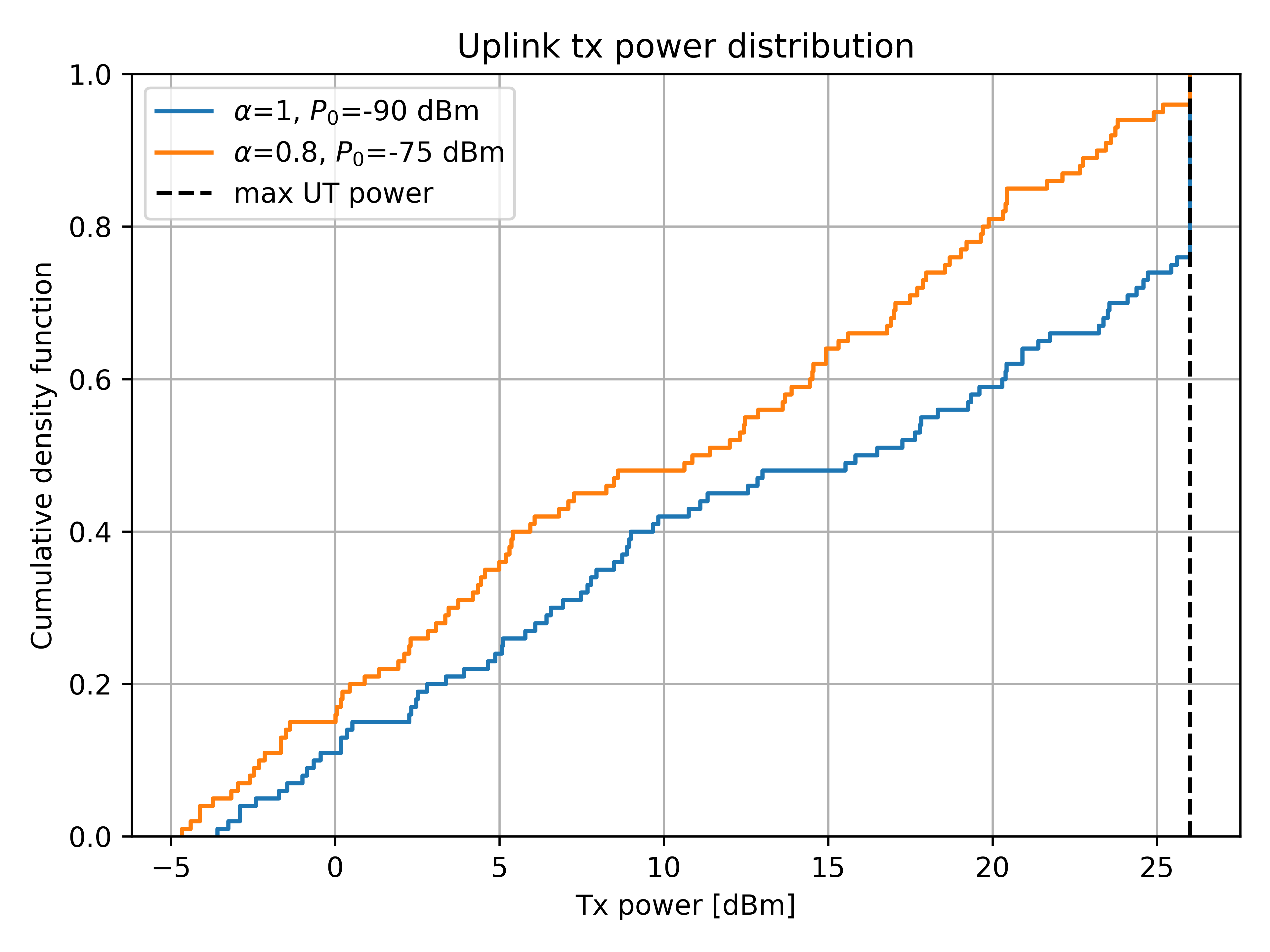
Examples
import torch
import matplotlib.pyplot as plt
from sionna.sys import open_loop_uplink_power_control
from sionna.phy import config
from sionna.phy.utils import db_to_lin, watt_to_dbm

# N. users
num_ut = 100
# Max tx power per UT
ut_max_power_dbm = 26  # [dBm]
# Pathloss [dB]
pathloss_db = config.rng.uniform(80, 120, size=(num_ut,))
# N. allocated subcarriers per UT
num_allocated_subcarriers = torch.full([num_ut], 40)
# Parameters (pathloss compensation factor, reference rx power)
alpha_p0 = [(1, -90), (.8, -75)]

for alpha, p0 in alpha_p0:
    # Power allocation
    tx_power_per_ut = open_loop_uplink_power_control(
        db_to_lin(pathloss_db),
        num_allocated_subcarriers=num_allocated_subcarriers,
        alpha=alpha,
        p0_dbm=p0,
        ut_max_power_dbm=ut_max_power_dbm)
    # Plot CDF of tx power
    plt.ecdf(watt_to_dbm(tx_power_per_ut).cpu().numpy(),
             label=fr'$\alpha$={alpha}, $P_0$={p0} dBm')
# Plot max UT power
plt.plot([ut_max_power_dbm]*2, [0, 1], 'k--', label='max UT power')

plt.legend()
plt.grid()
plt.xlabel('Tx power [dBm]')
plt.ylabel('Cumulative density function')
plt.title('Uplink tx power distribution')
plt.show()