HandheldUTArray#
- class sionna.phy.channel.tr38901.HandheldUTArray(carrier_frequency: float, polarization: str = 'single', polarization_type: str | None = None, antenna_locations: str | Sequence[int] = 'tr38901', antenna_pattern: str = '38.901-handheld', device_depth: float = 0.15, device_width: float = 0.07, port_power_offsets_db: Sequence[float] | None = None, precision: str | None = None, device: str | None = None)[source]#
Bases:
sionna.phy.object.ObjectHandheld UT antenna array from TR 38.901 Clause 7.3.
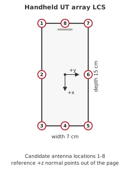
Fig. 17 Candidate antenna locations on the handheld UT device in the local \(x-y\) plane. The local \(z\)-axis is the reference orientation vector and points out of the shown plane.#
This class implements the handheld UT placement and field-rotation rules introduced by TR 38.901 V19.2.0 [TR38901V1920]. The element power pattern is selected through
AntennaElement; for standard-compliant handheld operation, useantenna_pattern="38.901-handheld", which follows Table 7.3-2. Antenna ports are placed at the candidate locations of Figure 7.3-2 on a flat device in the local \(x-y\) plane. The default dimensions are \(15\,\mathrm{cm}\) along the local \(x\)-axis and \(7\,\mathrm{cm}\) along the local \(y\)-axis. The reference orientation vector is the local \(z\)-axis, as shown in Figure 7.3-3.Note that this differs from the convention of
PanelArray, whose elements lie in the local \(y-z\) plane and share the boresight \(+x\). Here every port has its own boresight, pointing radially outward from the device center and hence lying within the device plane, so \(+z\) is not a boresight but the reference normal from which the polarization directions are derived.This class implements the same array interface as
PanelArrayand can be used as the UT array for theCDL,UMi,UMa,RMa,InH, andInFmodels. The antenna model is not tied to the channel-modelspec_versionargument. Selectingspec_version="19.2"enables the V19.2 propagation parameters, but is not required for this array class to run.TR 38.901 defines this geometry for a handheld UT. The common Sionna array interface also permits the object to be supplied in roles such as a BS array, but such use is not a standardized handheld-UT configuration.
- Parameters:
carrier_frequency (float) – Carrier frequency [Hz]. Used to establish the wavelength; calibration-frequency restrictions are not enforced.
polarization (str) – Polarization. One of
"single"or"dual".polarization_type (str | None) – Polarization type. For single polarization,
"V"uses the Clause 7.3 single-field polarization direction and"H"uses the orthogonal direction. For dual polarization,"cross"applies the 45 degree rotation described for two field patterns in Clause 7.3, while"VH"uses the unrotated orthogonal pair. The two-field configuration is not intended for FR1. Defaults to"V"for single polarization and"cross"for dual polarization.antenna_locations (str | Sequence[int]) – Candidate antenna locations from Figure 7.3-2; see Fig. 17. This can be a sequence of integers from 1 to 8,
"tr38901"for all eight candidates, or"tr38901-4"for the four-corner subset(1, 7, 3, 5)used by several TR 38.901 calibration assumptions. The numbering follows the figure: 1, 2, and 3 are on the left edge of the top-down view from top to bottom, 4 is the bottom edge center, 5, 6, and 7 are on the right edge from bottom to top, and 8 is the top edge center. Defaults to"tr38901".antenna_pattern (str) – Element radiation pattern. One of
"omni","38.901", or"38.901-handheld". Defaults to"38.901-handheld".device_depth (float) – Handheld-device extent along the local \(x\)-axis [m]. Defaults to 0.15 m.
device_width (float) – Handheld-device width [m]. Defaults to 0.07 m.
port_power_offsets_db (Sequence[float] | None) – Optional per-port attenuation [dB] for antenna imbalance. Positive values reduce the field amplitude. If set to None, no imbalance is applied, as specified by default in Table 7.3-2.
precision (str | None) – Precision used for internal calculations and outputs. If set to None,
precisionis used.device (str | None) – Device for computation (e.g.,
"cpu","cuda:0"). If None,deviceis used.
Examples
from sionna.phy.channel.tr38901 import HandheldUTArray

# Four single-polarized handheld antenna ports at locations 1, 7, 3, 5
ut_array = HandheldUTArray(carrier_frequency=7e9,
                           polarization="single",
                           antenna_locations="tr38901-4")
ut_array.show_element_radiation_pattern()

# Eight ports: two field patterns at the four corner locations
ut_array_dual = HandheldUTArray(carrier_frequency=15e9,
                                polarization="dual",
                                antenna_locations="tr38901-4")
ut_array_dual.show()
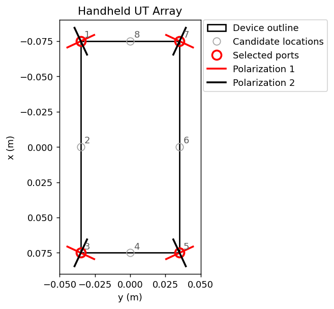
Fig. 18 Output of
show()for the dual-polarized array of the example above. Selected locations are drawn in red, unselected candidates in grey. The red segment shows the in-plane polarization direction of the first port of a location. The two polarizations are orthogonal in three dimensions, but their projections onto this top-down view coincide, so the second port is drawn as a perpendicular segment that marks the polarization pair rather than its true orientation.#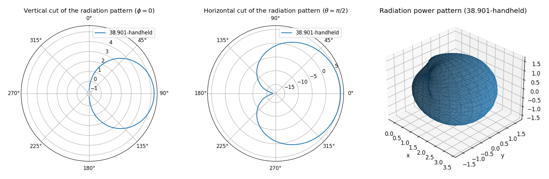
Fig. 19 Example output of
show_element_radiation_pattern()for the handheld UT reference antenna element.#Attributes
- property ant_ind_pol1: torch.Tensor#
Indices of antenna ports with the first polarization direction.
- property ant_ind_pol2: torch.Tensor#
Indices of antenna ports with the second polarization direction.
- property ant_pol1: sionna.phy.channel.tr38901.antenna.AntennaElement#
Reference element for the first polarization direction.
- property ant_pol2: sionna.phy.channel.tr38901.antenna.AntennaElement#
Reference element for the second polarization direction.
- property ant_pos: torch.Tensor#
Positions of the antenna ports [m].
- property ant_pos_pol1: torch.Tensor#
Positions of antenna ports with the first polarization direction.
- property ant_pos_pol2: torch.Tensor#
Positions of antenna ports with the second polarization direction.
- property candidate_pos: torch.Tensor#
Candidate antenna positions in the local coordinate system [m].
- property device_size: torch.Tensor#
Handheld-device size as
[depth, width][m].
Methods
- element_field(theta: torch.Tensor, phi: torch.Tensor) torch.Tensor[source]#
Compute per-port field vectors in the handheld-device LCS.
The incoming direction is first rotated into the local coordinate system of each candidate antenna, the reference field \(F_{\theta^{\prime\prime}}^{\prime\prime}\) or \(F_{\phi^{\prime\prime}}^{\prime\prime}\) is evaluated, and the field is then rotated back according to (7.3-6)–(7.3-8) of TR 38.901.
For the standard single-polarized handheld model, the boresight direction of candidate \(u\) is
\[\hat{\mathbf{b}}_u = \frac{\mathbf{r}_u}{\lVert\mathbf{r}_u\rVert}\]where \(\mathbf{r}_u\) is the candidate position relative to the handset center. With the reference handheld normal \(\hat{\mathbf{z}}\), the polarization direction is
\[\hat{\mathbf{p}}_u = \hat{\mathbf{b}}_u \times \hat{\mathbf{z}}\]which is parallel to the handheld plane and perpendicular to the direction from the handset center to the candidate location, as shown in Figure 7.3-7 of TR 38.901. The double-primed local basis is chosen such that the positive \(F_{\theta^{\prime\prime}}^{\prime\prime}\) component at boresight is aligned with \(\hat{\mathbf{p}}_u\).
- Parameters:
theta (torch.Tensor) – Zenith angle in the handheld-device LCS [radian].
phi (torch.Tensor) – Azimuth angle in the handheld-device LCS [radian].
- Output:
Tensor of shape
[num_ant] + theta.shape + [2]. The last dimension contains \((F_{\theta^\prime}^\prime,F_{\phi^\prime}^\prime)\).
- property port_basis: torch.Tensor#
Per-port local-to-device rotation matrices.
- property port_field_component: torch.Tensor#
Reference field component per port, 0 for theta and 1 for phi.
- property port_power_offsets_db: torch.Tensor#
Per-port antenna-imbalance attenuation [dB].