3GPP 38.901#
The submodule tr38901 implements 3GPP channel models from TR 38.901
V16.1 and V19.2 [TR38901V160100, TR38901V1920]. The version V19.2 is the default
and recommended selection. Version V16.1 is retained for reproducing the calibration
reference results and older experiments.
The CDL, UMi,
UMa, RMa,
InH, and
InF
models require setting-up antenna models for the transmitters and
receivers. This is achieved using the
PanelArray class.
For handheld UT antenna arrays defined by TR 38.901 Clause 7.3, use
HandheldUTArray.
The UMi,
UMa, RMa,
InH, and
InF
models require setting-up a network topology, specifying, e.g., the user
terminal (UT) and base-station locations, UT velocities, etc.
Topology generation is provided by Sionna SYS. The
SYS topology helpers return tuples that can be
passed directly to
set_topology(). In
particular, use gen_tr38901_multicell_topology() for TR
38.901 UMi/UMa calibration-style multi-cell drops,
gen_hexgrid_topology() for general UMi/UMa/RMa hexagonal-grid
drops, gen_tr38901_indoor_office_topology() for InH, and
gen_tr38901_indoor_factory_topology() for InF.
However, all models can be used with custom topologies as well.
Example#
The following example combines these components into a complete link-level setup: a panel array for the base stations, a handheld array for the UTs, the UMi model with spatial consistency enabled, and a topology helper that provides the geometry.
import torch
from sionna.phy.channel.tr38901 import HandheldUTArray, PanelArray, UMi
from sionna.sys import gen_tr38901_multicell_topology

device = "cuda:0" if torch.cuda.is_available() else "cpu"

# The antenna arrays, the channel model, and the topology helper must all
# use the same carrier frequency. It sets the wavelength that defines the
# element spacing and it selects the frequency-dependent parameter tables.
carrier_frequency = 3.5e9

# Base-station array: 2x2 cross-polarized elements, i.e., eight ports,
# with the sectorized element pattern of Table 7.3-1.
bs_array = PanelArray(num_rows_per_panel=2,
                      num_cols_per_panel=2,
                      polarization="dual",
                      polarization_type="cross",
                      antenna_pattern="38.901",
                      carrier_frequency=carrier_frequency,
                      device=device)

# UT array: handheld device of Clause 7.3 carrying four single-polarized
# ports at the corner candidate locations of Figure 7.3-2.
ut_array = HandheldUTArray(carrier_frequency=carrier_frequency,
                           polarization="single",
                           antenna_locations="tr38901-4",
                           antenna_pattern="38.901-handheld",
                           device=device)

# The channel model owns the scenario parameter tables and the generation
# pipeline. Spatial consistency correlates the LoS state and the
# small-scale parameters of UTs that are close to each other, instead of
# drawing them independently per UT.
channel_model = UMi(carrier_frequency=carrier_frequency,
                    o2i_model="low",
                    ut_array=ut_array,
                    bs_array=bs_array,
                    direction="downlink",
                    enable_spatial_consistency=True,
                    device=device)

# The topology helper builds the geometry: one ring of seven sites with
# three sectors each, hence 21 base stations, and one UT dropped per
# sector. It returns the tuple that set_topology expects, including the
# indoor/outdoor states and the wraparound virtual base-station positions.
topology = gen_tr38901_multicell_topology("umi",
                                          batch_size=1,
                                          num_ut_per_sector=1,
                                          carrier_frequency=carrier_frequency,
                                          num_rings=1,
                                          device=device)

# Hand the geometry to the model. The large-scale parameters as well as the
# cluster delays, powers, and angles are drawn here, and they are reused
# until the topology is set again.
channel_model.set_topology(*topology)

# Visualize the resulting drop, including the LoS state of every UT with
# respect to the base station selected by bs_index.
channel_model.show_topology()

# Sample channel impulse responses over 14 time steps spaced by 1/15 kHz.
# h has shape [batch size, num_ut, num_ut_ant, num_bs, num_bs_ant,
#              num_paths, num_time_samples] and holds the path
# coefficients; tau has shape [batch size, num_ut, num_bs, num_paths] and
# holds the path delays in seconds.
h, tau = channel_model(num_time_samples=14, sampling_frequency=15e3)
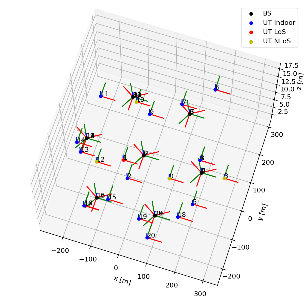
Fig. 12 Topology produced by the example, seen from an elevated viewing angle. The
seven sites of the single-ring layout each carry three co-located sectors,
drawn as black markers with their local coordinate systems. UT markers
distinguish indoor UTs from outdoor UTs in LoS and NLoS with respect to
base station bs_index=0.#
Because all system-level models share the same interface, replacing
UMi by
UMa,
RMa,
InH, or
InF only requires a matching topology and,
for some models, a different set of scenario-specific arguments.
Setting direction="uplink" swaps the roles of the two arrays, and the
resulting channel impulse responses can be turned into time-domain or
frequency-domain channel realizations as described in
the wireless channel overview.
|
Antenna panel array following the [TR38901V1920] specification |
|
Single antenna following the [TR38901V1920] specification |
|
Antenna element following the [TR38901V1920] specification |
|
Antenna array following the [TR38901V1920] specification |
|
Handheld UT antenna array from TR 38.901 Clause 7.3. |
|
Tapped delay line (TDL) channel model from the 3GPP [TR38901V1920] specification |
|
Clustered delay line (CDL) channel model from the 3GPP [TR38901V1920] specification |
|
Urban microcell (UMi) channel model from 3GPP [TR38901V1920] specification. |
|
Urban macrocell (UMa) channel model from 3GPP [TR38901V1920] specification. |
|
Rural macrocell (RMa) channel model from 3GPP [TR38901V1920] specification. |
|
Indoor hotspot (InH) channel model from 3GPP [TR38901V1920] specification. |
|
Indoor factory (InF) channel model. |